In pharmaceutical manufacturing, biotechnology, medical device production, and clinical laboratory applications, water is not a utility – it is a critical process material whose quality directly determines the safety, efficacy, and regulatory compliance of the products made using it.
Every tablet coating line, every injectable drug formulation, every bioreactor culture medium, every equipment cleaning and rinsing operation in a GMP facility depends on water that meets a precise, internationally defined quality standard. Ionic contamination at parts-per-billion concentrations can destabilise active pharmaceutical ingredients. Organic impurities can interfere with cell culture and analytical chemistry. Bacterial endotoxins at nanogram levels can cause life-threatening pyrogenic reactions in patients receiving injectable products.
This is why RO Filter TDS for USP Grade Water – defined by the United States Pharmacopeia with specifications adopted by the Indian Pharmacopoeia, WHO GMP, and international regulatory authorities worldwide – sets the quality benchmark for pharmaceutical water. And at the core of every USP water quality specification is the control of dissolved solids – measured and monitored through conductivity – which determines whether the water meets pharmacopeial standards or fails them.
Reverse osmosis filtration is the foundational technology in every USP water production system – performing the primary, bulk reduction of Total Dissolved Solids that makes downstream USP compliance achievable. But understanding exactly what role the RO filter plays in TDS control, what limitations it has, what additional treatment stages are required, and how the complete system must be designed and operated to consistently deliver USP-compliant water – is the technical knowledge that separates a well-engineered pharmaceutical water system from one that produces compliance failures, regulatory findings, and batch losses.
This complete technical guide by Bangalore Aqua – Karnataka’s No. 1 water treatment company – covers everything engineers, quality managers, procurement professionals, and facility operators need to know about RO filter TDS control for USP grade water: the standards, the limits, the system design, and the operational best practices that ensure consistent pharmacopeial compliance.

What Is USP Grade Water?
USP Grade Water is water whose chemical, physical, and biological properties meet the specifications defined in the United States Pharmacopeia (USP) – the authoritative compendium of pharmaceutical quality standards whose specifications are incorporated into the Indian Pharmacopoeia (IP), enforced under Schedule M GMP in India, and recognised by the USFDA, EMA, WHO, and virtually every major international pharmaceutical regulatory authority.
USP defines multiple grades of pharmaceutical water for different applications. The two grades with the most significant industrial relevance – and the most demanding TDS and conductivity specifications – are Purified Water and Water for Injection.
Purified Water (PW)
Purified Water is the standard pharmaceutical water grade used in the manufacture of non-sterile pharmaceutical products, for equipment and container cleaning and rinsing, in analytical laboratory applications, and as an ingredient or processing aid in pharmaceutical formulations that do not require sterile water.
USP Purified Water must be produced by a validated purification process – reverse osmosis, deionisation, distillation, or a combination – and must be stored and distributed in a system designed to prevent microbial contamination and maintain conductivity compliance at all times. It is defined by USP monograph <1231> and the associated conductivity, TOC, microbial, and chemical specifications that we cover in detail below.
Water for Injection (WFI)
Water for Injection is the highest purity grade of USP pharmaceutical water – required for the manufacture of sterile injectable drug products, large-volume parenterals, ophthalmic solutions, and dialysis water where any ionic, organic, particulate, or endotoxin contamination carries direct patient safety risk.
WFI meets all the same chemical purity specifications as Purified Water – including the same conductivity and TOC limits – with two additional critical requirements: a mandatory bacterial endotoxin limit of ≤ 0.25 EU/mL and a significantly stricter microbial action limit. The endotoxin requirement is the defining technical challenge that separates WFI production from Purified Water production – because endotoxins are not removed by RO membranes or EDI, requiring additional ultrafiltration or distillation stages.
Indian Regulatory Alignment
In India, the Indian Pharmacopoeia defines Purified Water and Water for Injection specifications that are closely harmonised with USP – with conductivity, TOC, microbial, and endotoxin limits that are essentially equivalent. Indian pharmaceutical manufacturers seeking USFDA, EU GMP, or WHO GMP certification – as well as those operating under domestic Schedule M requirements – must produce pharmaceutical water meeting these internationally harmonised standards, making USP compliance both a domestic regulatory obligation and a global market access requirement.
What Is TDS in Water?
Total Dissolved Solids (TDS) is the aggregate measure of all dissolved substances present in water – expressed as the total mass of dissolved material per unit volume of water, in milligrams per litre (mg/L) or equivalently parts per million (ppm).
What TDS Actually Measures
TDS encompasses every dissolved constituent in water – including:
Inorganic ions – Calcium (Ca²⁺), magnesium (Mg²⁺), sodium (Na⁺), potassium (K⁺), chloride (Cl⁻), sulfate (SO₄²⁻), bicarbonate (HCO₃⁻), nitrate (NO₃⁻), and other dissolved salts that constitute the mineral content of natural water sources
Heavy metals – Lead, arsenic, chromium, iron, manganese, and other trace metals present in groundwater or introduced through pipework and infrastructure
Dissolved organic compounds – Naturally occurring organic matter, agricultural chemicals, industrial pollutants, and water treatment chemical residues
Dissolved gases – Carbon dioxide, oxygen, and other gases dissolved in the water that affect pH and chemical reactivity
The ppm Concept for Pharmaceutical Applications
In the context of pharmaceutical water quality, TDS expressed in ppm (mg/L) gives a useful bulk measure of dissolved solid content – but it has a critical limitation for pharmaceutical applications: it does not distinguish between different types of dissolved substances, and it cannot be measured continuously and automatically in a production environment.
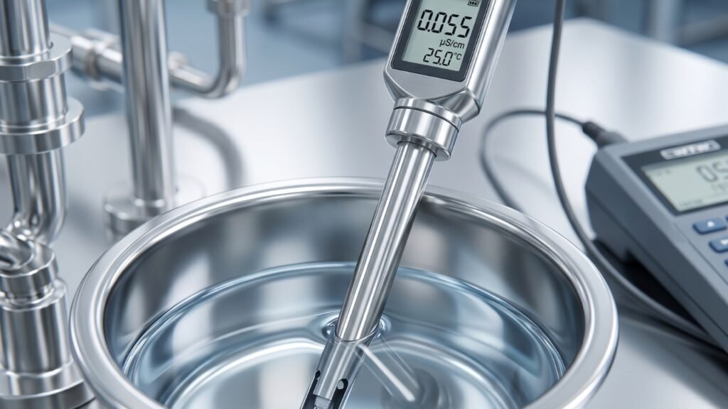
This is why the pharmaceutical industry – and the USP – primarily characterises and monitors dissolved solid content through electrical conductivity rather than direct TDS measurement. Conductivity – measured in microsiemens per centimetre (μS/cm) – measures the ability of water to conduct electricity, which is directly proportional to the concentration of dissolved ionic species. Because ionic contamination is the primary concern in pharmaceutical water purity, conductivity is a more specific, more sensitive, and more practically useful parameter than bulk TDS for pharmaceutical applications.
The relationship between TDS and conductivity is approximately: TDS (ppm) ≈ Conductivity (μS/cm) × 0.5–0.7 (depending on ionic composition). This approximation is useful for general reference but should not be used for precise pharmaceutical compliance determination – only calibrated conductivity measurement against USP specifications is appropriate for GMP compliance purposes.
USP Standards for Pharmaceutical Water Quality
The Critical Point – USP Defines Conductivity, Not TDS Directly
This is one of the most important technical points in this entire guide – and one that is frequently misunderstood by engineers and quality professionals new to pharmaceutical water system design.
The USP does not specify a direct TDS limit for Purified Water or Water for Injection. Instead, USP controls the ionic content of pharmaceutical water indirectly – and more rigorously – through a conductivity limit that is far more sensitive and discriminating than a TDS measurement could be.
USP <645> (Water Conductivity) defines a three-stage conductivity test for Purified Water and WFI – with Stage 1 being the primary real-time online monitoring specification:
Stage 1 (Online Monitoring): Conductivity ≤ 1.3 μS/cm at 25°C
This conductivity limit is the operational compliance specification – the value that must be continuously met at every point of use in the pharmaceutical water distribution system to ensure the water is fit for its intended pharmaceutical purpose.
The reason USP uses conductivity rather than TDS is precision. TDS measurement by gravimetric method (evaporation to dryness) has limited sensitivity and is impractical for continuous monitoring. Conductivity can be measured continuously, automatically, with calibrated online instruments at every sampling point – providing real-time assurance of compliance that a periodic TDS test cannot.
For practical engineering purposes, achieving the USP conductivity limit of ≤ 1.3 μS/cm corresponds to an approximate TDS of less than 1 ppm – a purity level dramatically higher than any natural water source and far beyond what standard water treatment technologies can achieve without the multi-stage purification train that we describe in detail below.
Complete USP Quality Specifications
| Parameter | USP Purified Water | USP Water for Injection |
| Conductivity (Stage 1) | ≤ 1.3 μS/cm at 25°C | ≤ 1.3 μS/cm at 25°C |
| Total Organic Carbon (TOC) | ≤ 500 ppb (0.5 mg/L) | ≤ 500 ppb (0.5 mg/L) |
| Bacterial Endotoxins | Not specified | ≤ 0.25 EU/mL |
| Microbial Action Level | ≤ 100 CFU/mL | ≤ 10 CFU/100 mL |
| Nitrates | ≤ 0.2 ppm | ≤ 0.2 ppm |
| Heavy Metals | ≤ 0.1 ppm | ≤ 0.1 ppm |
| pH | Not directly specified | Not directly specified |
The absence of a direct pH specification reflects the fact that pH in high-purity water is inherently unstable and difficult to measure accurately – and that conductivity provides a more robust and relevant ionic purity indicator for pharmaceutical purposes.
Typical TDS Range for USP Water – From Source to Compliance
Understanding the TDS transformation through each stage of a USP water production system – from raw source water to final pharmacopeial-compliant product – provides the engineering context for why each treatment stage is necessary and what it contributes.
| Water Stage | Typical Conductivity | Approximate TDS | USP Compliant? |
| Borewell Water (Bangalore/Karnataka) | 800 – 3000 μS/cm | 500 – 2000 ppm | No |
| Municipal Tap Water (Bangalore) | 200 – 600 μS/cm | 130 – 400 ppm | No |
| After Multimedia + Carbon Pre-treatment | 200 – 600 μS/cm | 130 – 400 ppm | No – pre-treatment does not reduce TDS significantly |
| After Water Softener | 150 – 500 μS/cm | 100 – 330 ppm | No – softening exchanges ions, slightly reduces conductivity |
| After Single-Pass RO | 10 – 50 μS/cm | 5 – 30 ppm | No – still 8–40× above USP limit |
| After Double-Pass RO | 2 – 10 μS/cm | 1 – 6 ppm | Borderline – not reliably compliant |
| After RO + EDI | 0.05 – 0.5 μS/cm | < 0.5 ppm | Yes – USP PW compliant |
| After RO + EDI + UV | 0.05 – 0.5 μS/cm (TOC reduced) | < 0.5 ppm | Yes – PW compliant with TOC control |
| USP Purified Water Limit | ≤ 1.3 μS/cm | < 1 ppm | Required |
| USP WFI Limit | ≤ 1.3 μS/cm + ≤ 0.25 EU/mL endotoxin | < 1 ppm | Required |
The critical engineering insight from this table is that the TDS reduction from raw water to USP compliance is a multi-order-of-magnitude transformation – from hundreds or thousands of ppm in source water down to less than 1 ppm in the final product. No single treatment technology achieves this transformation. It requires the integrated, sequential performance of pre-treatment, RO filtration, electrodeionisation, and ultraviolet treatment working together as a validated system.
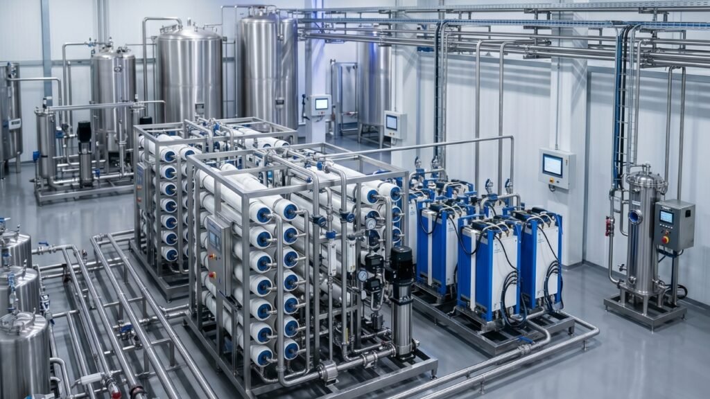
The Role of the RO Filter in TDS Reduction for USP Water
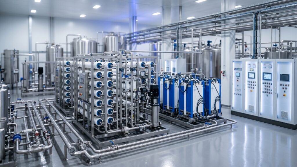
The industrial RO plant – or more specifically the RO membrane filtration stage – is the single most critical component in the TDS reduction train of a USP water production system. Understanding precisely what it does, how it does it, and what its limitations are is fundamental to designing a compliant and efficient pharma water system.
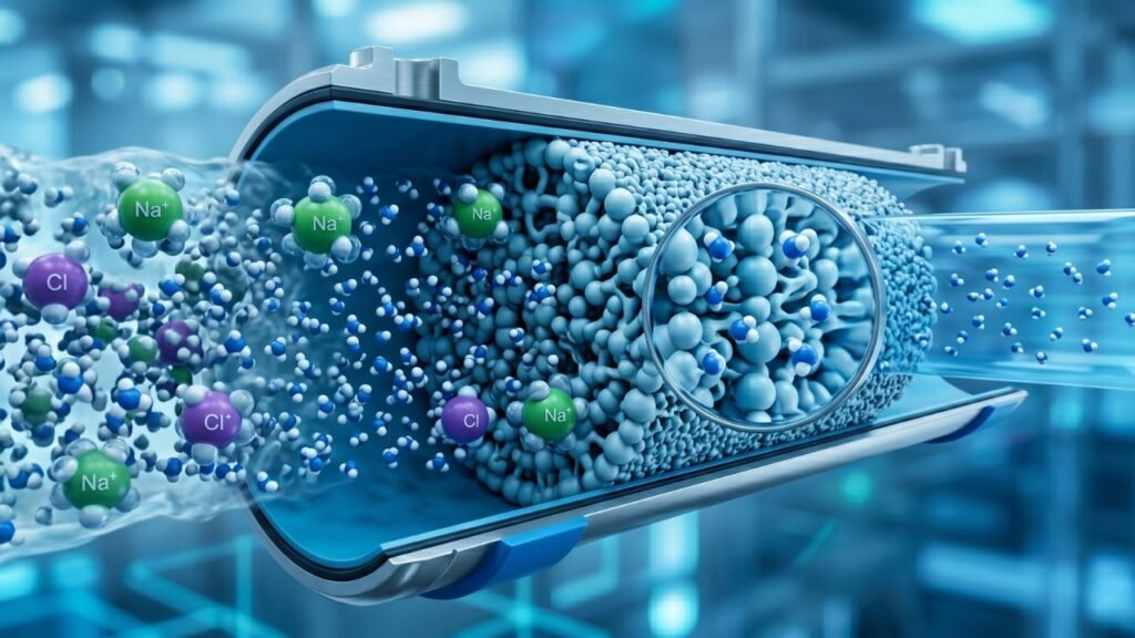
Membrane Separation – The Physics of RO TDS Rejection
Reverse osmosis achieves TDS reduction through a physical separation process based on the semi-permeability of the RO membrane. The membrane is a dense polymeric film – most commonly thin-film composite (TFC) with a polyamide active layer – with an effective pore structure at the molecular level that allows water molecules (molecular weight 18 Daltons) to pass through while rejecting dissolved ions and molecules above approximately 100–200 Daltons molecular weight.
When feed water is pressurised to the operating pressure of the RO system – typically 8–15 bar for brackish water membranes used in pharmaceutical RO applications – water molecules are forced through the membrane as permeate (product water), while dissolved ions, organic molecules, bacteria, viruses, and other contaminants are rejected and swept away in the concentrate (reject) stream that is discharged to drain.
The TDS rejection performance of a pharmaceutical-grade RO membrane is characterised by its rejection rate – the percentage of feed water TDS that does not appear in the permeate:
Rejection Rate (%) = (1 – Permeate TDS / Feed TDS) × 100
High-quality pharmaceutical-grade RO membranes achieve rejection rates of 97–99.5% for sodium chloride (the standard test solute) and similar rejection for most ionic species. For a feed water TDS of 500 ppm, a 99% rejecting membrane produces permeate with approximately 5 ppm TDS – reducing conductivity from approximately 800 μS/cm to approximately 8 μS/cm.
Rejection Performance Across Different Contaminant Types
RO membranes do not reject all dissolved species equally – and understanding the rejection hierarchy is important for system design:
| Contaminant Type | Typical RO Rejection Rate | Notes |
| Monovalent ions (Na⁺, Cl⁻, K⁺) | 95 – 99% | Lower rejection than divalent ions |
| Divalent ions (Ca²⁺, Mg²⁺, SO₄²⁻) | 97 – 99.5% | Higher rejection |
| Heavy metals | 95 – 99% | Varies by metal and pH |
| Dissolved organic compounds | 90 – 99% | Depends on molecular weight |
| Bacteria & viruses | > 99.9% | Physical size exclusion |
| Bacterial endotoxins | 0 – 50% | Poorly rejected – critical WFI limitation |
| Dissolved gases (CO₂, O₂) | < 10% | Gases pass freely through membrane |
The near-zero rejection of dissolved gases – particularly carbon dioxide – is a significant point for pharmaceutical water system design. CO₂ passes through the RO membrane into the permeate essentially unimpeded, where it dissolves to form carbonic acid – reducing permeate pH and contributing to conductivity that counts against the USP limit. Degassing after the RO stage is an important design element for systems targeting the lowest possible conductivity.
The poor rejection of bacterial endotoxins – large but uncharged lipopolysaccharide molecules that pass through or around RO membranes – is the fundamental reason why RO alone is insufficient for WFI production and why ultrafiltration is required as an additional stage for endotoxin removal.
Pre-Treatment – The Essential Foundation for RO Performance
The TDS rejection performance of the RO membrane is only as good as the pre-treatment that protects it. A fouled, scaled, or chemically damaged membrane cannot achieve its rated rejection rate – and membrane degradation progresses rapidly in the absence of adequate pre-treatment, producing permeate with rising TDS that undermines the entire downstream treatment train.
The critical pre-treatment requirements for pharmaceutical RO systems are:
Multimedia Filtration – Removes suspended solids, turbidity, and colloidal material (SDI reduction to < 5 is the standard pre-RO target) that would foul the membrane surface and reduce flux and rejection.
Activated Carbon Filtration – Removes free chlorine and chloramines – which irreversibly damage the polyamide active layer of TFC RO membranes – along with dissolved organic compounds. Chlorine removal is absolutely non-negotiable. Even brief chlorine exposure at typical municipal water concentrations of 0.5–1.0 mg/L can cause detectable membrane degradation, and cumulative exposure causes progressive rejection loss that cannot be reversed.
Water Softening – Removes calcium and magnesium hardness that causes carbonate scaling on the membrane surface – the most common cause of membrane flux decline in RO systems operating on hard water sources like most of Bangalore’s municipal and borewell supply. Softening feed water to < 1 mg/L hardness is standard practice for pharmaceutical RO systems.
Antiscalant Dosing – Chemical dosing upstream of the RO to inhibit the precipitation of calcium carbonate, barium sulfate, silica, and other scale-forming compounds on the membrane surface – complementing the softener’s hardness removal and protecting against scale-forming species that the softener does not address.
5-Micron Cartridge Filtration – Final barrier filtration immediately upstream of the RO high-pressure pump to remove any particulates that passed through the multimedia filter and protect the pump and membrane from abrasive particle damage.
Why the RO Filter Alone Is Not Enough for USP Compliance
This is the most important engineering reality that every pharmaceutical facility, hospital, and industrial user deploying an RO-based water treatment system must understand – and one that is unfortunately still misunderstood in many installations across India.
A single-pass RO system, regardless of membrane quality, cannot reliably achieve USP Purified Water conductivity compliance.
The mathematics are straightforward and unforgiving. A 99% rejecting RO membrane processing feed water with conductivity of 500 μS/cm (a typical Bangalore municipal water value) produces permeate with conductivity of approximately 5 μS/cm. The USP limit is 1.3 μS/cm. The RO permeate is nearly 4 times above the specification limit – and that gap cannot be closed by choosing a “better” membrane or optimising RO operating conditions within normal parameters.
Even a double-pass RO system – two RO stages in series – typically achieves permeate conductivity of 2–5 μS/cm for typical Indian source water, which while dramatically better than single-pass still does not reliably meet the 1.3 μS/cm USP limit with the consistency required for GMP validation.
The fundamental limitation is that RO rejection, however excellent, is a ratio – a percentage. There will always be a non-zero concentration of ions in the RO permeate, and for high-TDS source water like Bangalore borewell water at 1000+ μS/cm, even 99.5% rejection leaves 5+ μS/cm in the permeate – still well above USP limits.
Achieving USP-compliant Conductivity USP water requires the addition of a polishing stage downstream of RO that can reduce the residual ionic content of the RO permeate to the sub-0.1 μS/cm range. The technology that achieves this – reliably, continuously, and without chemical regeneration – is Electrodeionisation (EDI).
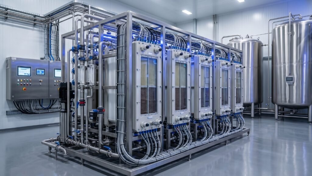
Why EDI Is Required After RO
EDI combines ion exchange resin with ion-selective membranes and a direct electrical current to continuously remove the residual ionic contaminants from RO permeate that the membrane alone cannot eliminate. The electrical current continuously regenerates the ion exchange resin – without the acid and caustic chemical regeneration cycles required by conventional mixed-bed deionisers – delivering a continuous product stream with conductivity of 0.05–0.1 μS/cm, well within the USP Purified Water limit of 1.3 μS/cm.
The combination of RO (bulk TDS reduction, 95–99%) + EDI (final ionic polishing to < 0.1 μS/cm) is the standard, validated process train for USP Purified Water production in the modern pharmaceutical industry – replacing the older RO + mixed-bed deionisation approach that required chemical regeneration and batch operation.
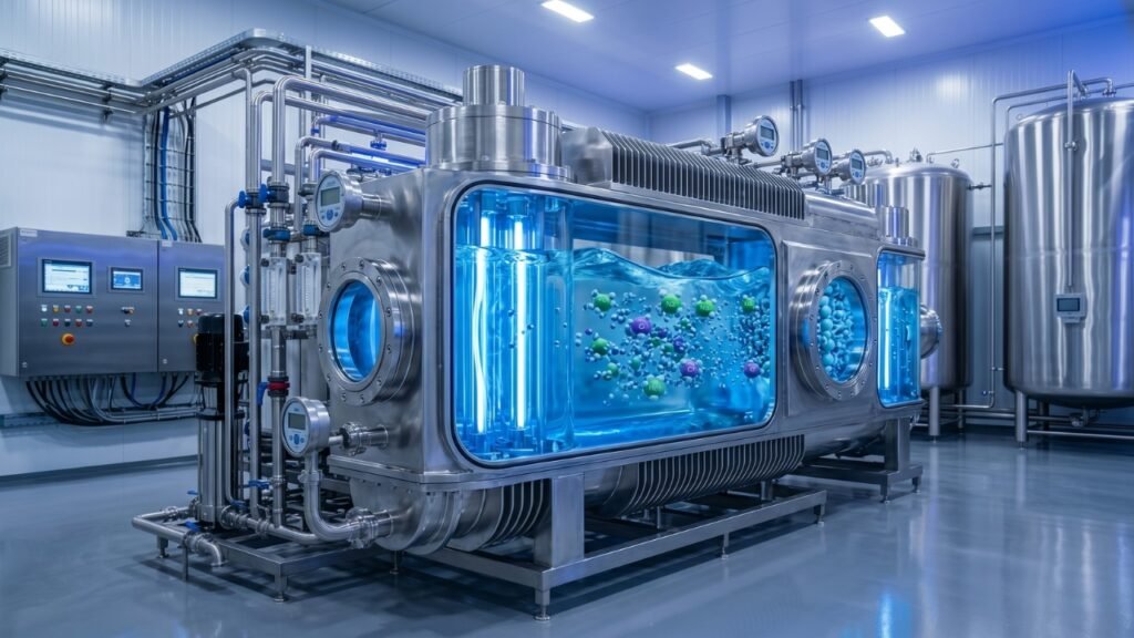
Why UV Is Required After EDI
UV disinfection serves two distinct and essential functions in the pharmaceutical water treatment system:
254 nm UV – Microbial inactivation – Installed at multiple points in the system including after RO, after EDI, and in the recirculation distribution loop, 254 nm UV inactivates bacteria, viruses, and other microorganisms – maintaining the low bioburden required for USP microbial action limit compliance.
185 nm UV – TOC reduction – 185 nm UV photooxidises dissolved organic compounds in the water, breaking them down into CO₂ and water and reducing TOC levels toward the USP limit of ≤ 500 ppb. This is particularly important for systems where RO and EDI treatment alone does not achieve TOC compliance, or where the distribution system introduces trace organic contamination from system materials.
Why Ultrafiltration Is Required for WFI
For Water for Injection production, a final ultrafiltration stage with a molecular weight cut-off of approximately 6,000–10,000 Daltons is required to achieve the bacterial endotoxin specification of ≤ 0.25 EU/mL. Endotoxins – large lipopolysaccharide molecules – are not effectively rejected by RO membranes or removed by EDI, and must be specifically targeted by UF membranes or distillation. The USP has approved membrane-based WFI production (RO + EDI + UF) as an equivalent alternative to traditional multi-effect distillation.
Complete USP Water System Design – Process Flow & Engineering Specifications
The complete validated process train for USP Purified Water production follows this sequence:
Raw Water Inlet → Multimedia Sand Filter → Activated Carbon Filter → Water Softener → Antiscalant Dosing → 5μm Cartridge Filter → High-Pressure RO Pump → RO Membrane Array (Single or Double Pass) → CO₂ Degasser → EDI Module → UV (254 nm + 185 nm) → Purified Water Storage Tank (316L SS) → Recirculation Distribution Loop → UV (254 nm, in-loop) → Points of Use
For WFI: Add Ultrafiltration (UF) after UV, before storage
Stage-by-Stage Engineering Specifications
Pre-Treatment Train
The pre-treatment system must achieve the following minimum performance targets at its outlet to protect the downstream RO membrane:
Turbidity < 1 NTU, SDI₁₅ < 5 (< 3 preferred for sensitive membranes), Free chlorine < 0.1 mg/L (< 0.05 mg/L for maximum membrane protection), Total hardness < 1 mg/L as CaCO₃ (post-softener), Antiscalant dosed at manufacturer-specified concentration for the site-specific scale-forming ion concentrations.
RO Membrane Stage
Pharmaceutical-grade RO systems should be specified with the following design parameters:
Membrane type – Thin-film composite (TFC) polyamide, pharmaceutical-grade with documented rejection performance and extractable substance compliance. Recovery rate – 60–75% for pharmaceutical applications (balancing water conservation with membrane performance and scaling risk). Operating pressure – 8–15 bar depending on feed water TDS and membrane specification. Flux rate – Conservative flux (< 20 L/m²/h for pharmaceutical membranes) to minimise concentration polarisation and maximise rejection. Instrumentation – Online conductivity measurement of permeate and reject streams, feed and permeate pressure gauges, flow meters on permeate and reject, and automatic diversion of off-spec permeate.
For feed water TDS above 500 ppm (common in Bangalore borewell water applications), double-pass RO configuration is strongly recommended to reduce the EDI inlet conductivity to < 20 μS/cm – within the optimal operating range of the EDI module.
EDI Module
EDI inlet water quality requirements – critical for EDI performance and longevity:
Conductivity < 20–40 μS/cm (double-pass RO preferred for > 500 ppm feed water), Free chlorine < 0.02 mg/L (absolute – chlorine destroys EDI ion exchange resin and membranes), Hardness < 1 mg/L as CaCO₃, Iron < 0.01 mg/L, Total organic carbon < 0.5 mg/L, Temperature 5–35°C.
EDI outlet performance specifications: Conductivity < 0.1 μS/cm (resistivity > 10 MΩ·cm), TOC – marginal contribution from EDI itself, dependent on feed water TOC.
UV System
254 nm germicidal UV dose: Minimum 30 mJ/cm² for standard pharmaceutical water applications; 40+ mJ/cm² for WFI pre-UF applications. 185 nm TOC-reduction UV: Installed in the main product stream for TOC reduction where required. In-loop recirculation UV: 254 nm germicidal UV in the distribution recirculation loop – sized for the loop recirculation flow rate to deliver the required UV dose to the entire recirculating water volume at the loop turnover frequency.
Storage & Distribution System
316L electropolished stainless steel storage tanks and distribution pipework – internal surface Ra ≤ 0.8 μm. Continuous recirculation at minimum 1 m/s velocity throughout the distribution loop. Temperature – ambient (15–25°C) for Purified Water loops; 80°C+ for hot WFI loops that maintain temperature as the primary biocontamination control measure. Online continuous conductivity and TOC monitoring at the system outlet and at representative points of use. Automatic diversion of off-spec water to drain.
Common Issues in RO-Based USP Water Systems
Issue 1 – Membrane Fouling Causing Rising Permeate TDS
Symptom: Gradual increase in RO permeate conductivity over weeks or months – trending upward from initial commissioning values toward and eventually above the pre-EDI design specification.
Causes: Inadequate pre-treatment allowing suspended solids, colloidal fouling, or biological fouling to accumulate on the membrane surface. Scaling from calcium carbonate, silica, or other scale-forming species not adequately controlled by the softener and antiscalant. Progressive membrane ageing – all membranes lose some rejection performance over their operational life.
Consequences: Rising RO permeate conductivity increases the ionic load on the downstream EDI module beyond its design capacity – leading to EDI outlet conductivity rising toward and eventually above the USP limit. If not detected and addressed promptly, membrane fouling causes cascading quality failures through the entire downstream treatment train.
Prevention and Response: Maintain pre-treatment performance rigorously – replace pre-filters on schedule, verify softener regeneration frequency and brine concentration, confirm antiscalant dosing rate. Monitor RO normalised permeate flow and normalised salt passage on a weekly basis – these normalised performance indicators detect fouling-related performance decline before it becomes a quality problem. When normalised salt passage has increased by 10–15% above baseline, perform Clean-In-Place (CIP) membrane cleaning using appropriate cleaning agents for the identified fouling type.
Issue 2 – EDI Outlet Conductivity Above USP Limit
Symptom: EDI product water conductivity above 1.3 μS/cm – directly failing the USP Purified Water specification.
Causes: RO permeate conductivity too high for EDI capacity (most common cause – pre-treatment or RO membrane performance issue). Chlorine breakthrough from carbon filter exhaustion – chlorine irreversibly damages EDI resin and ion exchange membranes within hours of exposure. EDI ion exchange resin exhaustion or fouling. EDI electrical supply failure or control system fault. CO₂ in feed water – dissolved CO₂ contributes conductivity that EDI does not efficiently remove.
Prevention and Response: Monitor carbon filter effluent chlorine level daily – replace carbon filter media on schedule regardless of other performance indicators. Install online chlorine monitoring with automatic system shutdown upstream of the EDI module. Install a CO₂ degasser or membrane degassing unit between the RO stage and EDI inlet. Maintain RO permeate conductivity well within EDI design specifications at all times. Conduct regular EDI performance verification – inlet vs outlet conductivity – and investigate any trend deterioration promptly.
Issue 3 – Microbial Out-of-Specification Events
Symptom: Microbial counts at points of use exceeding the USP action limits – ≤ 100 CFU/mL for Purified Water or ≤ 10 CFU/100 mL for WFI.
Causes: Biofilm establishment in distribution loop dead legs, low-velocity pipe sections, or sampling valves. Inadequate UV dose in the distribution loop allowing microbial proliferation in the recirculating water. Infrequent or ineffective system sanitisation. Storage tank contamination through inadequate vent filtration or improper access.
Prevention and Response: Design and maintain the distribution loop to eliminate dead legs and stagnation zones. Maintain recirculation velocity above 1 m/s at all points in the loop. Verify UV lamp intensity and dose regularly – UV lamp output degrades over time (typically 9,000–12,000 hours operational life) and lamps must be replaced on schedule regardless of whether they are still illuminated. Conduct periodic hot water or chemical sanitisation per documented SOP. Increase sampling frequency and locations at the first sign of any microbial trend deterioration.
Issue 4 – Poor Maintenance and Documentation Failures
Symptom: Not a water quality symptom but a regulatory one – GMP inspection findings related to inadequate maintenance records, out-of-calibration instruments, missing validation documentation, or absence of change control for system modifications.
Causes: Treating the pharmaceutical water system as a utility rather than a critical process system. Inadequate preventive maintenance scheduling. Failure to maintain calibration status of conductivity, TOC, and flow measurement instruments. Absence of validated procedures for maintenance, sanitisation, and system changes.
Prevention: Implement a comprehensive water system maintenance management programme – scheduled preventive maintenance tasks with documented completion records, calibration schedules for all online and offline measurement instruments, SOPs for all operational and maintenance activities, and a change control procedure for any modification to the validated system.
Best Practices for RO Filter TDS Control in USP Water Systems
Regular Monitoring – TDS, Conductivity & System Performance
Continuous online monitoring of conductivity at critical system points – RO permeate, EDI outlet, and every point of use – is a non-negotiable requirement for GMP-compliant USP water system operation. The monitoring programme should include:
Daily checks: Verify online conductivity readings at all monitoring points are within specification and alert limits. Check UV lamp status indicators. Verify recirculation pump operation and loop flow rate.
Weekly checks: Review and trend conductivity and TOC data. Calculate and trend normalised RO performance parameters (normalised permeate flow, normalised salt passage). Check antiscalant dosing system operation and chemical inventory. Verify softener regeneration frequency and brine concentration.
Monthly checks: Full water quality testing – conductivity, TOC, microbial counts, and targeted chemical analysis at multiple system sample points. Review all instrument calibration status. Confirm pre-filter differential pressure within specification.
Quarterly checks: Comprehensive system performance review – trending all monitored parameters against baseline values. Evaluate pre-filter replacement schedule based on differential pressure trends. Conduct enhanced microbiological sampling programme. Verify UV lamp output using calibrated radiometer.
CIP Cleaning – Protocols and Frequency
Clean-In-Place (CIP) membrane cleaning is the primary maintenance intervention for restoring RO membrane performance when fouling has caused normalised salt passage to increase beyond the 10–15% trigger threshold.
Effective CIP protocols require matching the cleaning chemistry to the fouling type:
Carbonate and metal hydroxide scale – Low-pH cleaning with citric acid (2% w/v, pH 4, 35°C, 60 minutes recirculation) effectively dissolves carbonate scale. Citric acid is preferred over hydrochloric acid for pharmaceutical systems due to lower corrosion risk and easier waste disposal.
Biological fouling and organic foulants – High-pH cleaning with sodium hydroxide (0.1% w/v, pH 12, 35°C, 60 minutes) effectively removes biofilm and organic foulants. Sodium lauryl sulfate can be added for enhanced surfactant action against heavy biological fouling.
Silica fouling – High-pH cleaning with elevated temperature (45°C) is most effective. Silica fouling is one of the most difficult membrane fouling types to clean and is best prevented through antiscalant dosing specifically formulated for silica inhibition.
After CIP, thorough flushing with pre-treated feed water until permeate pH returns to near-feed-water values is essential before returning the system to USP water production service.
System Validation – The GMP Imperative
A USP water system in a GMP pharmaceutical environment must be validated – demonstrating through documented commissioning, qualification, and performance testing that it consistently produces water meeting USP specifications under all anticipated operating conditions. Validation follows the standard pharmaceutical qualification lifecycle:
Design Qualification (DQ) – Documents that the system design meets the intended USP water grade requirements and applicable regulatory standards.
Installation Qualification (IQ) – Documents that the system has been installed correctly according to the approved design and manufacturer specifications.
Operational Qualification (OQ) – Documents that the system operates within its design parameters across the intended operating range – including challenge testing at worst-case operating conditions.
Performance Qualification (PQ) – Typically conducted over a minimum 1-year period following a defined phased approach (Phase 1: 2–4 weeks intensive daily testing; Phase 2: 2–4 weeks reduced testing; Phase 3: routine monitoring) – demonstrating consistent USP compliance over seasonal variations in source water quality and normal operational variability.
The validation programme must include documented sampling plans, analytical methods with validated procedures, acceptance criteria, and out-of-specification (OOS) investigation procedures – providing the complete documented evidence base that demonstrates and assures ongoing USP compliance.
Also Read on Bangalore Aqua Blog
- How to Soften Hard Water — Easy, Natural & Affordable Methods for Indian Homes
- How RO Systems Achieve USP Grade Water: TDS Control & Purification Process
- Why Your Fish May Die in RO Water (And How to Fix It)
- RO Water Tank: Types, Benefits, Working & How to Choose the Right One
- Does 316 Stainless Steel Rust with RO Water? Causes, Myths & Prevention Guide
- RO Filter TDS for USP Grade Water: Standards, Limits & System Design Guide
Conclusion
The relationship between RO filter TDS reduction and USP Grade Water compliance is one of the most practically important technical topics in pharmaceutical water system design – and understanding it correctly is the difference between a system that reliably delivers pharmacopeial compliance and one that produces intermittent failures, regulatory findings, and production losses.
The key engineering principles this guide has established are:
RO filtration is foundational but insufficient alone – It performs the critical primary TDS reduction from hundreds of ppm in source water to 5–50 ppm in the permeate. But single-pass RO permeate, even from a high-quality pharmaceutical-grade membrane, is typically 4–40 times above the USP conductivity limit of 1.3 μS/cm.
USP compliance requires conductivity control, not just TDS reduction – The USP defines water quality through conductivity specification, which is more specific, more sensitive, and more practically measurable than direct TDS for pharmaceutical purposes.
EDI is the essential polishing technology after RO – Electrodeionisation reliably achieves the sub-0.1 μS/cm conductivity required for USP Purified Water compliance – continuously, chemically free, and without the batch downtime of conventional deionisation.
UV is a mandatory biological and TOC control measure – At both 254 nm for microbial inactivation and 185 nm for TOC reduction, UV is an essential component of the complete USP water production train.
Pre-treatment quality determines RO membrane performance – The entire downstream system performance ultimately depends on the quality and consistency of the pre-treatment protecting the RO membrane. Inadequate pre-treatment is the most common root cause of RO performance degradation and downstream USP compliance failures.
Validation, monitoring, and maintenance are not optional – A technically correct system design that is not properly validated, continuously monitored, and rigorously maintained will not deliver consistent USP compliance. These are not administrative requirements – they are the operational practices that convert a correctly designed system into a reliably compliant one.
For pharmaceutical manufacturers, hospitals, biotechnology facilities, and industrial users in Bangalore and across Karnataka who need to design, install, upgrade, or validate a USP-grade water production system – Bangalore Aqua brings the technical expertise, system design capability, quality component supply, and long-term maintenance support to deliver a complete solution that performs to pharmacopeial specification from day one and continues to do so reliably throughout its validated operational life.
📞 Call / WhatsApp: +91 76763 93939 | +91 97387 04753
📧 Email: info@bangaloreaqua.com
🌐 Visit: bangaloreaqua.com
Karnataka’s No. 1 Water Treatment Company – delivering pharmaceutical-grade water systems, industrial RO plants, and complete water treatment systems for pharma, biotech, healthcare and industrial clients across Bangalore and Karnataka since 2021.